1. An overview of the
1.1 Scope of application
Many important occasions, the load of electricity reliability is very important. In order to meet the needs of these important loads, the general power supply system is powered by dual power supply, such as dual mains, one road mains and one road UPS. However, the more reliable method is to use double UPS power supply, such as many IDC room, telecommunications, mobile, many important loads in the power system are using this power supply method. For double power supply, how to safely, quickly and effectively switch directly affect the electricity reliability of load, especially many devices acceptable outage time is extremely harsh, such as: request outage time should not exceed 10 ms, some even require 5 ms, in the face of such requirements, general ATS, such as mechanical contact is unable to accept this assignment, and high-speed static non-contact switch and fast power detecting fast, safe and effective implementation of double power supply switch, meet the demand of these occasions. Our company research and development of AC dual power switching device to meet the thermal power plant ETS, MFT, DEH and other systems to achieve dual AC power switching, reliable and uninterrupted power supply to ensure the normal operation of ETS, MFT, DEH and other systems.
1.2 Device architecture features
☆Standard 2U 19-inch reinforced unit case is designed to resist strong vibration and interference and is suitable for harsh environments.
☆The device has high stability and reliability.
☆Adopt LCD, Chinese menu human-computer interface, easy to operate, simple and easy to learn.
☆Intelligent design, working parameters can be adjusted in the module.
☆Mean time free from failure (MTBF) is not less than 100,000 hours.
☆Powerful communication function, support RS485 communication and alarm dry contact signal.
2. The main function
The main functions of the device are as follows:
☆ Switching function
☆ Self detection function
☆ Overvoltage protection function
☆ Current limiting protection function
☆ Over-current protection function
☆ Event alarm function
☆ Communication function
2.1 Description of switching function
The RSTS AC dual power switching device adopts the latest digital control technology and new SCR power devices to realize fast switching between two AC power sources.
2.2 Description of self-detection function
The device has the function of self-check. On the one hand, the device hardware real-time self-check, once the hardware fault occurs, immediately lock the device, and report the cause of the fault for easy maintenance.
2.3 Description of overvoltage protection function
There is an input voltage setting value inside the device (user setting), once the input voltage and user setting voltage value does not match, the device will automatically lock, interrupt the output.
2.4 Description of current limiting protection function
The device can adjust the output current value (range: 10A-300A) according to the needs of the site. In case of grounding, excessive output current will cause damage to the equipment and ensure the normal operation of the equipment.
2.5 Description of overcurrent protection function
When the external short circuit accident occurs, the device will automatically lock the output circuit to avoid affecting the other AC circuit to cause the accident expansion, and send out an alarm signal.
2.6 Description of event alarm function
The device has alarm function for various events: self-checking events, operation events and control events. Users can query the action time, event name and other record information through the LCD "Event Recall" page.
2.7 Communication function
The device is equipped with an RS485 serial port to upload the real-time status of the device to DCS, which is convenient for DCS to monitor and manage the running equipment.
3.Technical index
3.1 Device rating dataEntry name | Technical index |
Rated output power | 44KVA |
Switching time | Priority switch | ≤2Ms |
Power off switching | ≤5Ms |
AC input | Rated voltage (VAC) | 220 |
Rated frequency (Hz) | 50 |
Rated current (A) | 30~200 |
Power factor | 1 |
Automatic conversion of threshold voltage | 220Vac±12.5%,Return difference ± 5V |
Automatic conversion of threshold
frequency | 50Hz±10%,Return difference±0.2Hz |
Overrun protection shutdown threshold
voltage | 220Vac(176~264Vac) |
Over-limit protection shutdown threshold frequency | ≤42.5Hz or ≥57.5Hz,Return difference±0.2Hz |
Overload capacity |
Load current < 105%, continuous operation
The load current is 105 ~ 125%, lasting for 10min
The load current is 125-150% for 1min
Load current > 150%, 60mS shutdown
|
Environment condition | Insulation strength | 2KVAC,1min |
Noise(1m) | <40dB |
Working environment temperature | -20~55℃ |
Transportation and storage temperature | -40~70℃ |
Humidity | 0~90%,Non-condensing |
Altitude(m) | ≤3000 1500~3000m 1% output derating per 100m increase |
3.2 Environmental conditions
☆ Working temperature: -20℃ ~ +55℃.
☆ Storage temperature: -30℃ ~ 80℃, relative humidity is not more than 80%, the surrounding air does not contain acid, alkaline or other corrosive and explosive gases, rainproof, snow proof room; Under the limit value, no excitation is applied, and no irreversible change occurs to the device. After the temperature is restored, the device can work normally.
☆ Relative humidity: the monthly average maximum relative humidity of the wettest month is 90%, while the monthly average minimum temperature of the month is 25℃ and the surface is not condensed. When the highest temperature is +40℃, the average maximum humidity does not exceed 50%.
3.3 Electrical interference performance
☆ Pulse group interference
The device can withstand pulse group interference test with frequency of 1MHz and 100kHz attenuated oscillation wave (voltage amplitude of the first half wave is 2.5kV common mode and 1kV differential mode) stipulated by GB/T14598.13-1998.
☆ Fast transient interference
Device can withstand the GB/T14598.10-1996 in the fourth chapter of harsh level for Ⅳ transient interference test.
☆ Radiated electromagnetic interference
The device can withstand the radiation electromagnetic field interference test of grade IV as specified in chapter 4 of GB/T14598.9-1995.
☆ Electrostatic discharge
The device can withstand the severe grade IV ESD test specified in 4.1 of GB/T14598.14-1998.
☆ Surge (shock) immunity
The device can withstand the surge (shock) immunity test of grade IV according to GB/T17626.5-1999.
3.4 Insulation performance
☆ Insulation resistance
Each live conductive circuit is respectively to the ground (that is, the shell or exposed non-charged metal parts); Alternating current loop and voltage loop, with the open circuit voltage of 500 v test instrument test the insulation resistance should not be less than 100 m ?.
☆ Strength of medium
Each live conductive circuit is respectively between the ground (that is, the shell or exposed non-charged metal parts); Between the AC current loop and the AC voltage loop, it can withstand the AC voltage of 50Hz and 2KV (effective value). After 1min test, there is no breakdown or flashover phenomenon.
☆ Impulse voltage
The charged conducting terminals are respectively between the ground, the AC current loop and the AC voltage loop, and can withstand the standard lightning shock test of 5kV (peak).
3.5 Mechanical properties
☆ Vibration response
Device can withstand the GB/T11287-2000-2 in harsh level for Ⅰ vibration response of the inspection.
☆ Impact response
Device can withstand the GB/T14537-1993 2 in harsh level for Ⅰ shock response test.
☆ Vibration durability
Device can withstand 4.2.2 specified in GB/T11287-2000 severe grade level for Ⅰ vibration endurance test.
☆ Impact durability
Device can withstand 4.2.2 specified in GB/T14537-1993 severe level for Ⅰ impact durability test.
A collision being
Device can withstand the GB/T14537-1993 4.3 in harsh level for Ⅰ collision test.
3.6 Working range and allowable error of each component
☆ Voltage element
2V ~ 100V/400V: error no more than ±2.5%
☆ Time element
Within 20s (including 2s) : no more than ±40ms, and no more than ±2% of the setting value above 2s
3.7 Measurement accuracy
☆ The measurement error of each analog quantity shall not exceed ±1.0% of the rated value.
☆ The resolution of the switch is 1ms.
5. Structure and panel definitions
5.1 Structure of chassis
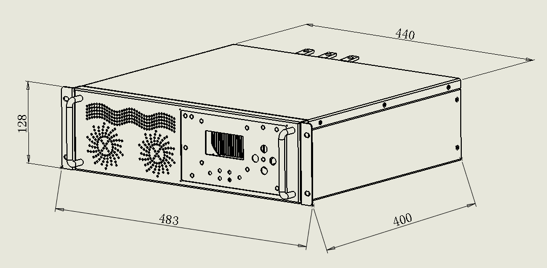
The device adopts the whole panel form, the panel is equipped with liquid crystal display, signal indicator light, operation keyboard, communication interface, etc.
The unit case is 19-inch 3U reinforced unit case, designed to resist strong vibration and strong interference. Ensure the high reliability of the device when it is installed in the field under harsh conditions. The external dimensions of the device are shown in Figure 5.1. The mounting hole size (width × depth × height mm) of the device is ≤ 483×440×128, as shown in Fig. 5.1. The size of the chassis will be changed according to the current size, and the actual size will prevail
5.2 definition of key and indicator
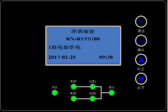
Status indicator light: There are 6 red and green double-color indicator lights on the front panel of the AC dual power switching device. The specific meanings of the lights are shown in the table below:
Indicator light | State | Significance |
Power 1 indicator | Green is always bright | The voltage and frequency of power supply 1 are normal |
Red is always bright | Abnormal voltage or frequency of power supply 1 |
Power 2 indicator | Green is always bright | The voltage and frequency of power supply 2 are normal |
Green is always bright | Abnormal voltage or frequency of power supply 2 |
SCR1 indicator | Green always on and off | SCR1 is turned on and the system is powered by one power supply |
SCR1 off |
Scr2 indicator | Green always on and off | Scr2 is turned on and the system is powered by one power supply |
SCR2 close |
Output indicator | Green always on and off | The system is output by the main power supply |
The system has no output |
Red is always bright | The system is output by standby power supply |
Status indicator | Green is always bright | Normal operation |
Red is always bright | System fault (such as fan fault, power board fault, abnormal input power supply, overload, over temperature, etc.) |
Key: four keys to operate the display liquid crystal, the meaning of each key is as follows
 :LCD menu up or parameter minus one key
  : LCD menu down or parameters plus one button
 :LCD menu OK key
  :LCD menu exit key
6. The man-machine operation
The man-machine page consists of indicator light, buttons, and LCD screen. As described in the previous hardware description, please refer to Section V Structure and Panel Definition. The following will briefly introduce the main content and operation of each LCD page, all interfaces are divided into boot interface, main interface, menu interface. Users can easily browse the system input, output, load data, timely access to the system's current state and alarm information, and carry out the relevant function Settings and control operations. LCD can also provide up to 1000 historical alarm records for user inquiry, to provide reliable basis for fault diagnosis.
6.1 Description of boot interface and main interface
After the device is powered on or reset, the display interface is shown in Figure 6.1

Figure 6.1.1 power on page
Ming said:
1) The startup interface displays the company name and model, and the running status and time of the system are displayed in real time.
After the device starts up and displays the startup interface, press the "down" button to enter the main interface, which has 2 pages:
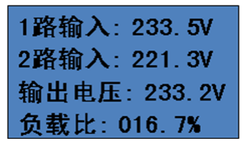
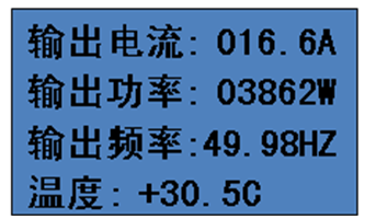
Figure 6.1.2 main interface page 01 Figure 6.1.3 main interface page 02
Ming said:
1) From the boot screen, press the next page to enter the main screen. The main screen displays the operating data of the system in real time on 2 pages, which can be turned from the previous or the next page;
2) Page 01 of the main interface displays 1-channel input voltage, 2-channel input voltage, system output current and output load percentage;
3) Page 02 of the main interface shows the output current, power and frequency of the system and the internal temperature of the system.
6.2 Menu interface operation methods and instructions
6.2.1 How to enter a password
Press "Next" on page 02 of the main interface to enter the menu interface. When the arrow points to time setting, press "OK" to enter the time setting password input interface. Only when the password is correctly entered can the time setting interface be entered. In addition, the parameter setting and control command all need to enter the password before the next operation. Take time setting password input as an example to explain the specific steps as follows:
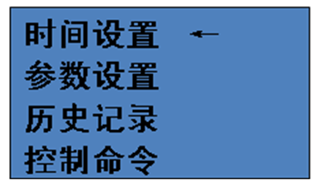
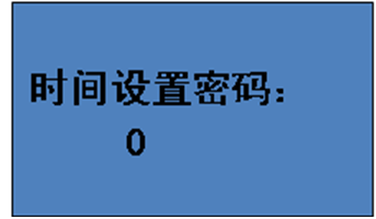
Figure 6.2.1.1 menu interface Figure 6.2.1.2 correct input of time setting password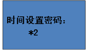
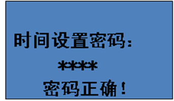
Figure 6.2.1.3 second digit of password input Figure 6.2.1.4 6-digit password input is correct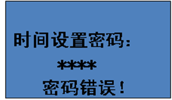
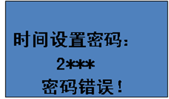
Figure 6.2.1.5 6-digit password input error Figure 6.2.1.6 changing the wrong password
Ming said:
1) After entering the password input interface (Figure 6.2.1.2), it will be prompted to input the first password. At this time, press the previous page or the next page to add or subtract 1 to this bit. Set up after the first press the confirmation key automatically jump to the second (figure 6.2.1.3), according to the previous page or a page at this time to add 1 or 2 minus 1, so on to the sixth password and press the confirmation key, if the password is correct, it will appear as shown in figure 6.2.1.4 interface, if the wrong password will appear as shown in figure 6.2.1.5 prompt interface. Enter the correct password and then press the OK button to enter the time setting. (The record clearing or command function is automatically completed when the password is entered correctly.) If the password is incorrectly entered, continue to press the "Enter" button to enter the first password again (Figure 6.2.1.6) until the password is correctly entered. Press the "Exit" button to return to any interface for password input to set the selection interface (Figure 6.2.1.1).
2) All passwords on the machine are 1234, and the password input method is the same in all places where the password is needed.
6.2.2 How to set the system time
Press "Next" on page 02 of the main interface to enter the menu interface. When the arrow points to time setting, press "OK" to enter the time setting password input interface. After the password is correctly entered, the time setting interface is as follows:
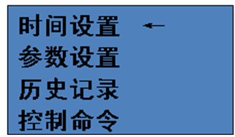
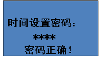
Figure 6.2.2.1 menu interface Figure 6.2.2.2 time setting password input is correct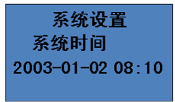
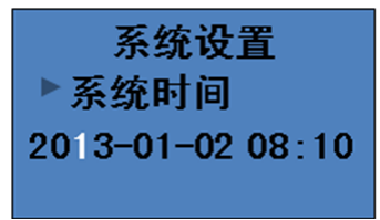
Figure 6.2.2.3 system time setting Figure 6.2.2.4 ten digit setting of system time year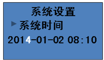
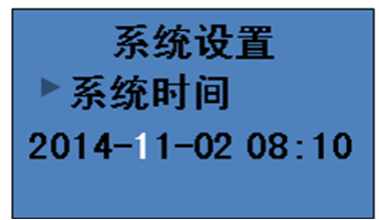
Figure 6.2.2.5 system time year bit setting Figure 6.2.2.6 ten digit setting of system time month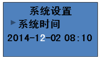
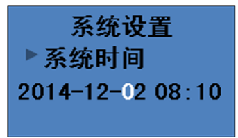
Figure 6.2.2.7 system time month bit setting Figure 6.2.2.8 ten digit setting of system time day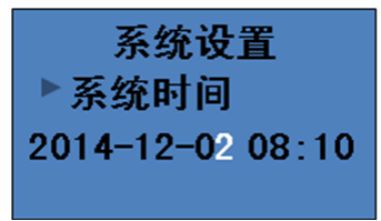
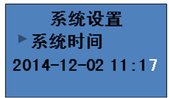
Figure 6.2.2.9 system time, day and bit setting Figure 6.2.2.10 system time bit setting
Ming said:
1) After entering the time setting interface of the system (Figure 6.2.2.3), press the "OK" button and an anti-white prompt will appear to set the time;
2) figure 6.2.2.4 against white tip in ten sets, according to the previous page or a page for 10 years to add or subtract 1 operation, set up in 10 press confirm automatically jump to the years after the end, after every set up according to confirm button after a jump to the next until the end points, points of bits set (figure 6.2.2.10) press to confirm the white tip disappear, after the current time to set a good time.
3) Time Setting Press the Exit key to return to the menu interface as shown in Figure 6.2.2.1.
6.2.3 How to set parameters
Press "Next" on page 02 of the main interface to enter the menu interface. Press "Next" when the arrow points to parameter setting, press "OK" to enter the parameter setting password input interface. Enter parameters when the password is correctly entered
The setting interface is as follows:
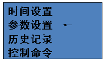
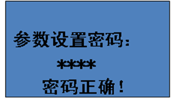
Figure 6.2.3.1 menu interface Figure 6.2.3.2 parameter setting password input is correct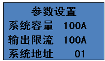
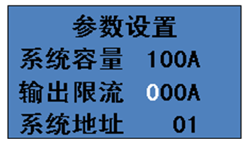
Figure 6.2.3.3 parameter setting interface Figure 6.2.3.4 setting of output current limiting 100 bits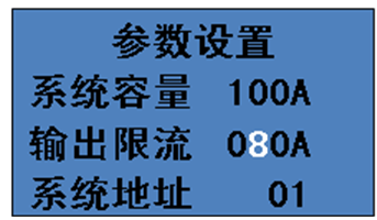
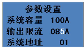
Figure 6.2.3.5 ten bit setting of output current limiting Figure 6.2.3.6 setting of output current limiting bit
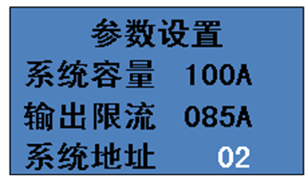
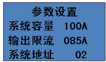
Figure 6.2.3.7 system address setting Figure 6.2.3.8 parameter setting completed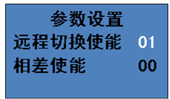
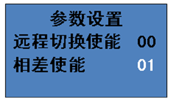
Figure 6.2.3.9 remote switch enable settings Figure 6.2.3.10 phase difference enable setting
Ming said:
1) After entering the system time setting interface (Figure 6.2.3.3), press the "OK" button and an anti-white prompt will appear to set the parameters;
2) figure 6.2.3.4 against white tip output current limit of one hundred, according to the previous page or a page for 10 years to add or subtract 1 operation, set up the output current limit according to confirmed after a one hundred - bit key automatically jump to the output current limit of 10, after each set of output current limit according to confirm key jump into bits, after ten bits set (figure 6.2.3.6) press the confirmation key to address system after the white tips, according to confirm after system address set key, the white tip disappear, the current parameters to set good parameters (figure 6.2.3.6). If the output current limiting ratio of the system capacity is automatically set as the value of the system capacity after the anti-white is gone, to prevent the overload caused by the configuration error from burning out the device.
3) Parameter Settings Press the "Exit" button to return to the menu interface as shown in Figure 6.2.3.1.
4) After entering the system time setting interface (Fig. 6.2.3.3), press the "Next" button to enter the remote switching setting and phase difference enabling setting interface. After that, press the OK button to set the anti-white prompt parameters. The next and previous pages can set these two parameters to two values, 01 (allowed) and 00 (forbidden), and only these two values can be set. After the parameters are set, press the "OK" button, the anti-white prompt disappears. The setting is completed, and then press the "OK" button to exit.
6.2.4 How to view history
Press "Next" on page 02 of the main interface to enter the menu interface. Press "Next" when the arrow points to history, press "OK" to enter the history viewing interface. The details are as follows:
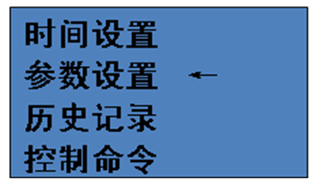
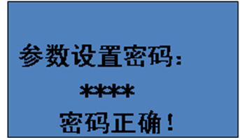
Figure 6.2.4.1 main menu interface Figure 6.2.4.2 history interface
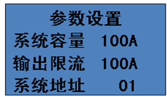
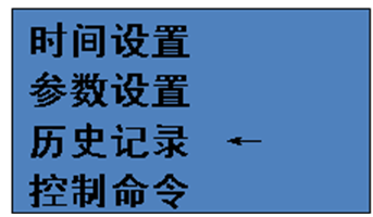
Figure 6.2.4.3 page hundred setting Figure 6.2.4.4 ten digit page setting
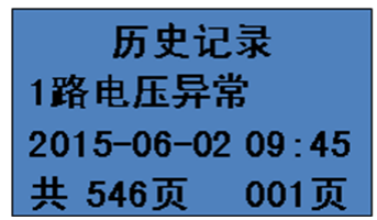
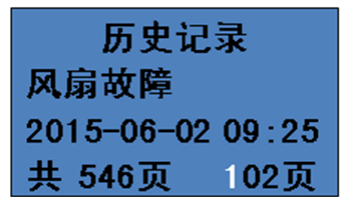
Figure 6.2.4.5 ten digit page setting Figure 6.2.4.6 page number setting completed
Ming said:
1) The history record interface displays the fault state and the time when the fault occurs during the operation of the system, as shown in Fig. 6.2.4.2. The fourth is the total number of records and the current page number; Press the next page directly to turn to the next page and add one page accordingly.
2) After entering the history record interface (Fig. 6.2.4.2), press the "OK" button to show the anti-white prompt of the hundred digit of the current page number, as shown in Fig. 6.2.4.3. At this time, press the previous or next page to add or subtract 1 to the hundred digit of the current page number. Press the "OK" button after setting the "hundred" digit, and the "ten" anti-white prompt will appear as shown in Figure 6.2.4.4. The "ten" digit is also set by adding or subtracting 1 from the previous or the next page. After setting the ten bits, jump to the one bit setting as shown in Figure 6.2.4.5. After setting the one bit, the anti-white prompt disappears, and the record automatically jumps to the record corresponding to the set page number.
3) Press the Exit button to return to the selection interface of history as shown in Fig. 6.2.4.1;
6.2.5 How to control the system
When the arrow points to the control command, press "OK" to enter the sub-menu interface of the control command. Select the command corresponding to the arrow and press "OK" to enter the password. After the password is correct, the system will execute corresponding operations. The details are as follows:
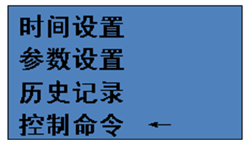
Figure 6.2.5.1 main menu interface
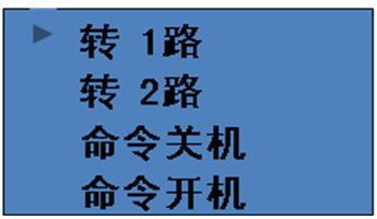
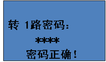
Figure 6.2.5.2 select turn 1 command Figure 6.2.5.3 turn to 1 channel, the password is correct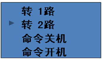
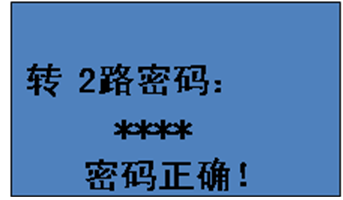
Figure 6.2.5.4 select 2-way command Figure 6.2.5.5 turn to 2-way, correct password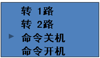
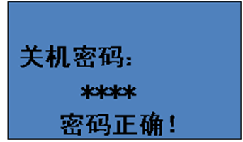
Figure 6.2.5.6 select shutdown command Figure 6.2.5.7 correct shutdown password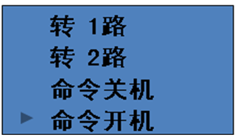
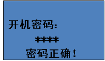
Figure 6.2.5.8 select boot command Figure 6.2.5.9 power on password is correct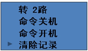
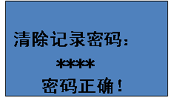
Figure 6.2.5.10 select clear record command Figure 6.2.5.11 clear record password is correct
Ming said:
1) Under the control command item of the main menu interface, there are 5 system control commands: Turn 1, Turn 2, Command Start, Command Shutdown and Clear Record. The system will execute the corresponding actions if the password of the corresponding command is correct.
2) Press the Exit button on any password input interface to return to the superior selection interface of corresponding command (Figure 6.2.5.2, 6.2.5.4, 6.2.5.6, 6.2.5.8, 6.2.5.10).
6.3 Warning information
When the AC dual power switching device is in working state, if the status indicator light turns red, it indicates an alarm. Check the history record to know when the system has a fault, and the specific meaning of the fault is shown in the table below:
Table 6-3 Alarm List
Give an alarm | Explain |
Abnormal voltage of 1 circuit | The voltage of one power supply is out of the normal range. Check 1-way input phase voltage |
Abnormal 2-way voltage | The voltage of the two power supplies is out of the normal range. Check 1-way input phase voltage |
Over load | The output load exceeds the set output current limit range |
Over temperature fault | If the temperature of heat sink exceeds 75 ℃, the system will shut down for protection |
Auxiliary power failure | The auxiliary power supply inside the machine is abnormal |
Auxiliary board fault | The auxiliary power board inside the machine is abnormal |
Fan failure | At least one fan has failed |
System shutdown | System shutdown without output |
Output overvoltage | The output voltage is higher than 250V |
Output low voltage | The output voltage is lower than 190V |
Abnormal communication | Communication failure between main control board and display board |
SCR1 fault | SCR1 short circuit or open circuit fault |
Scr2 fault | Scr2 short circuit or open circuit fault |
Abnormal frequency of 1 channel | The frequency of one power supply is out of the normal range |
Abnormal frequency of 2 channels | The frequency of the two power supplies is out of the normal range |
7 Installation Environment
To ensure the normal operation of the AC Dual Power Switcher, install the AC Dual Power Switcher in a controlled environment. At the same time, in order to avoid overheating of the AC dual power switching device, please keep the AC dual power switching device ventilated smoothly, the ventilation holes and fans can not be blocked by debris, the front and back from the wall distance is not less than 600mm. The installation site of AC dual power switching device must meet the following conditions:
1) close to the power supply, easy distribution.
2) Clean and dust free environment.
3) The altitude shall not exceed 1000m. If the altitude exceeds 1000m, it shall install the relevant national standard for capacity reduction for use.
4) The ambient temperature is -5 ~ 50℃, and the relative humidity does not exceed 90%.
5) No corrosive, explosive and insulating gas and conductive dust, and away from heat source.
6) No vibration and jolt, and the vertical inclination is not more than 5%.
7) AC dual power switching device, such as in the air conditioning environment (about 20℃) operation, will improve the reliability and prolong the service life.
8. Backboard terminal wiring instructions and equipment installation
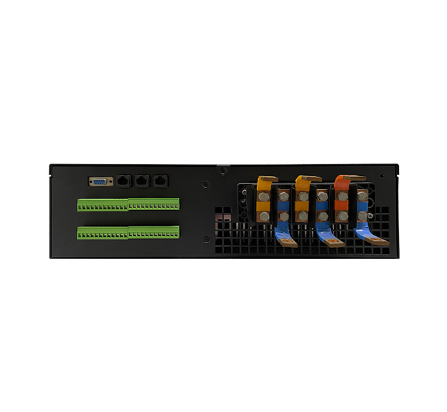
The overall front view of the device is shown in Figure 8.1

Figure 8.1
The overall schematic diagram of device backplane terminal is shown in Figure 8.2

Figure 8.2
8.2 Back terminal description
The specific meaning of each part of the back panel of the AC dual power switching device is as follows:
Power terminal
L1 | N | L2 | N | Lout | N | PE |
Input/INPUT | Output/OUTPUT | Earth |
1) 1 channel AC input: 1 channel input terminal of AC dual power switching device, L1 and N are connected to fire line and zero line respectively
2) 2-channel AC input: 2-channel input terminals of AC dual power switching device, L2 and N are connected to fire line and zero line respectively
3) AC output: output terminal of AC dual power switching device, Lout and N are output fire line and output zero line respectively
4) PE (earth) : AC double power switching device grounding wire
Communication terminal
1) RS485 communication: using RJ45 terminal, where 1: RS485A 2: RS485B
2) Parallel interface: using RJ45 terminal, including 1: RS485A and 2: RS485B
3) RS232 communication: DB9 terminal is used for debugging
Dry contact terminal
Dry contact interface | Signal definition | System failure | The system is normal | Main circuit fault | Standby fault | Fault 01 - fault 03 | Remote switch |
Interface terminal | 1 | 2 | 3 | 4 | 5 | 6 | 7 | 8 | 9 | 10 | 11 | 12 | | | | 22 | 23 | 24 |
Explain | Signal effectively connected to normally open | Signal effectively connected to normally open | Signal effectively connected to normally open | Signal effectively connected to normally open | Standby signal | |
Normally open | 2-3 | 5-6 | 8-9 | 11-12 | | 22-23 |
Normally closed | 1-2 | 4-5 | 7-8 | 10-11 | | 23-24 |
Note: The voltage and current of the contact are DC. It is 220VDC/0.4A output signal.
1) System alarm: when any fault occurs to the device, the effective public contact of the drive signal of the group is connected to the normally open contact
2) The system is normal: when there is no fault in the device, the effective public contact of the driving signal of the group is connected to the normally open contact
3) Main road alarm: when the control command selects AC input 1 or AC input 2 output, the main road power supply. When the main road power supply is abnormal, the effective public contact of the drive signal of this group switches from normally closed contact to normally open contact;
4) Standby alarm: when the control command selects AC input 1 or AC input 2 output, the main power supply of this road and the other power supply is the standby power supply. When the standby power supply is abnormal, the effective public contact of the drive signal of this group switches from the normally closed contact to the normally open contact.
5) Failure 01-03:3 contacts are reserved as standby
6) Remote switching: the remote switching control normally open contact is short or normally open contact is disconnected, the switching signal is effective, the system is switched to the standby power supply.
9.User instructions
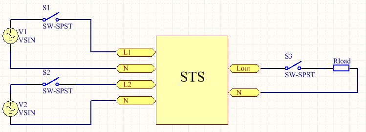
Figure 9.1 user wiring diagram
After the input and output power wires and ground wires are connected, as shown in Figure 9.1, please ensure that the voltage of the input power supply is within the normal range (190V-250V) before switching on the switch (S1 or S2) of any power supply. If the voltage of the two power sources is not in the normal range after closing the switch, the system will not be able to output. The default of the system is 1 way first. After starting up, the 1 way will become the priority power supply if the command is sent at any time. After sending the command to turn 2, 2 will become the preferred power supply. The output indicator light is green, indicating that the current power supply is the priority power supply, and red indicates that the current power supply is the standby power supply. So control commands can be sent directly from the display if the current power supply priority is not what the user expects.
Switching control commands sent locally by the display are invalid when remote switching enabler is enabled.
If the phase difference between the two input power sources is large and there is a large inductance at the output end of the power supply, it is necessary to set the phase difference energy parameter to 01. In order to ensure that the system will not be shut down due to common protection during switching, the output power off time will exceed 5ms during switching.
Difference enablement specification:
The test wiring is shown in Figure 9.1. If the phase difference between V1 and V2 is large, and the STS input power supply is knocked out due to the disconnection of S1 or S2, and the power supply needs to be switched to both external and one-way power supply, the power down time will exceed 5ms due to the excitation current of T1 or T2, so as to ensure that the system will not shut down due to common protection during the switching. If S3 or S4 is disconnected, there is no need to set the difference enable, and the power down time is within 5ms.
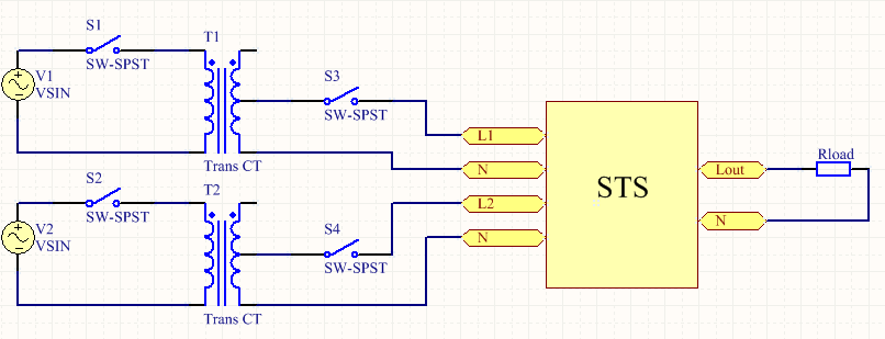
Chart 9.2




 :LCD menu up or parameter minus one key
  : LCD menu down or parameters plus one button
 :LCD menu OK key
  :LCD menu exit key


