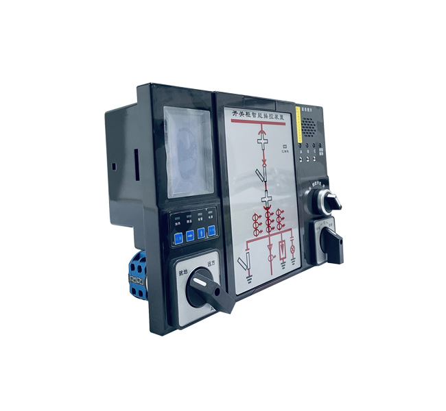
Working power supply
|
DC 110V~300V or AC 85~265V
|
Work environment
|
Temperature:-20℃~+70℃ Humidity:≤95%RH
|
Ambient temperature measurement range
|
-20℃~+80℃
|
Measuring range of contact temperature
|
-20℃~+150℃
|
Heating interface
|
Passive output (load < 300W)
|
Cooling interface
|
Passive output (load < 300W)
|
Contact temperature measurement alarm interface
|
Passive output (load < 300W)
|
Forced locking interface
|
Passive output (load < 300W)
|
Dielectric strength
|
≥AC2000V
|
Insulation performance
|
≥100MΩ
|
Temperature accuracy
|
≤±1℃
|
Humidity accuracy
|
≤±2%RH
|
Dynamic flicker frequency
|
1Times / s
|
Human proximity sensing time
|
≤3s
|
Communication interface
|
RS485(Quarantine),Adopt MODBUS-RTU communication protocol
|
RS485 communication distance
|
<1200m
|
Baud rate
|
1200BPS, 2400bps, 4800bps, 9600bps can be set
|
Status indication mode
|
The relationship between input and LED digital display is dynamic configuration
|
Anti electromagnetic interference performance
|
According to iec255-22
|
Type of temperature sensor
|
Wireless transmission of induction power
|
Receiving and transmitting distance of wireless module
|
Up to 30 meters in open space
|
LCD resolution
|
1℃
|
一、Simulated display parts and functions (Note: the following picture is a conventional mask, the specific mask is subject to the real object)
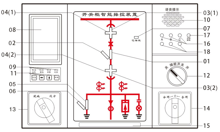
01 Closing indication of circuit breaker 10 Voice output
02 Sub indication of circuit breaker 11 Operation keyboard
03(1) 03 (2) working position indication 12 Energy storage knob
04(1) 04 (2) test position indication 13 Remote / local transfer switch
05 Closing indication of grounding switch 14 On / off transfer switch
06 Sub indication of grounding switch 15 Human telepathy
07 Energy storage indication 16 Live display
08 LCD display interface 17 Atresia
09 Indicator area 18 Phase checking
1.1. Circuit breaker status display
When the circuit breaker is closed and the switch circuit is intact, the red 01 analog strip will emit light.
When the circuit breaker is disconnected and the closing circuit is intact, the green 02 analog strip will emit light.
1.2 Hand car position display
Passive contact input, when the working position contact is closed, red 03①, 03② vertical analog bar light, indicating that the circuit breaker is located in the working position.
When the test position contact is closed, the green 04① and 04② horizontal analog bars light up, indicating that the circuit breaker is located in the test position.
When the handcar is located between the test position and the working position, the light bars 03①, 03② and 04①, 04② flash simultaneously.
When the handcart is moved out of the switch cabinet, the red 03①, 03② and the green 04①, 04② light strips are not luminous, indicating that the handcart has been cut off.
1.3 Display of ground switch position
Passive contact input is closed, red 05 vertical analog bar is illuminated, indicating the grounding switch is closed;
The passive contact input is disconnected, the green 06 oblique analog bar is illuminated, and the grounding switch is disconnected.
1.4 Spring energy storage display
Passive contact closed, yellow 07 light light, indicating that the circuit breaker has stored energy.
1.5. Live display and locking function
LED starting voltage (KV) : three phases are charged at the same time, rated phase voltage × (0.15 ~ 0.65).
Lock start-control voltage (KV) : three phases are charged at the same time, rated phase voltage ×0.65.
When the three phases are not charged at the same time, the latching release lamp is on, and the electromagnetic lock action is started.
1.6 Automatic heating and dehumidification control and digital display of temperature and humidity
It can be equipped with two temperature and humidity sensors to display the temperature and humidity values of the field environment, and users can set the upper and lower limits of heating/dehumidification/exhaust output according to their needs. When the ambient humidity is greater than the upper limit of the set humidity or the ambient temperature is less than the lower limit of the set temperature, start heating; When the ambient humidity is less than the lower limit of the set humidity and the ambient temperature is greater than the upper limit of the set temperature, stop heating; When the ambient temperature is more than 50℃, stop heating unconditionally to prevent overheating damage.
1.7. Human body sensor probe
When someone stands in front of the cabinet, start the automatic lighting inside the cabinet.
1.8. Manual lighting
Press the lighting key in the operation keyboard to manually start the lighting in the cabinet (there are two words above the display screen), and repeat the key to close the manual lighting.
1.9. Intelligent voice anti-false prompt function
When the circuit breaker is in the closing state and the handcart is mistakenly pushed from the test position to the working position, the voice prompts "Please separate the circuit breaker".
When the ground switch is in closing state and the handcar is mistakenly pushed from the test position to the working position, the voice prompts "Please separate the ground switch".
When the circuit breaker is in the closing state and the ground switch is in the closing state, and the handcar is mistakenly pushed from the test position to the working position, the voice prompts "Please separate the circuit breaker and the ground switch".
When the main circuit of the cabinet sends power, the voice prompts "this circuit has been charged".
1.10. Switch and transfer function
The device panel is equipped with open/close switch (or button), remote/local switch, energy storage switch and other operation switches, convenient for users to operate.
1.11. Communication function
The device has RS485 communication interface, using Modbus-RTU protocol, bort rate 1200bps~9600bps can be set.
1.12. Disconnection alarm function of temperature and humidity sensor
When the host does not detect the temperature and humidity sensor signal, the display will display --.
1.13. Wireless temperature measurement function
It can measure the temperature of multiple electrical contacts at the same time. When the measured temperature is greater than the set tripping and alarm value, the device will output tripping or alarm signal. Each host is standard equipped with 3~9 point temperature measurement (can receive the maximum temperature of 15 measuring points). Contact temperature sensor adopts inductive power acquisition method to independently obtain working power supply, and in the responsible current range of 5A~5000A and above for a long term continuous and stable operation, to achieve maintenance free high voltage electrical contact temperature monitoring.
1.13.1 Structure and installation
1.1. Sensor contour structure diagram:
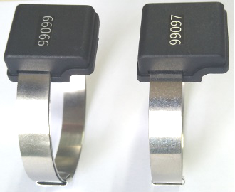
Sensor outline drawing

Structural dimension drawing of sensor
1.2. Installation of temperature sensor
It is mainly installed on the movable contact of the switch cabinet circuit breaker, and the fixed switch cabinet is installed in a binding type near the switch switch contact.
1) The cabinet should be power off before installation.
2) take electrical alloy belt into the temperature sensor and two fixed silica gel pad, the temperature sensor is fixed at the bottom of the moving contact contact refers to the upper surface of clubs and began after fixed installation location to determine the location, the alloy with end across the other side of card buckle and slowly tighten, tighten the lock your card buckle with tools, such as near the breaker fixed tank after installing breaker can revolve around the arm a little plastic taut, complete the installation.
1.3. Installation examples
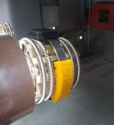
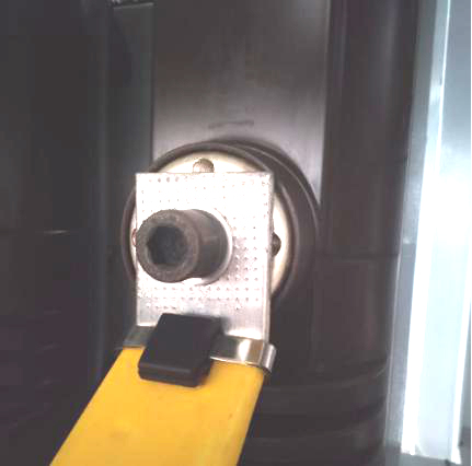
1.13.6、Application framework of wireless temperature measuring device
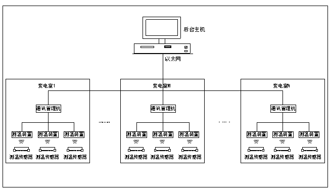
二、Installation dimension and wiring diagram
2.1、Installation dimension
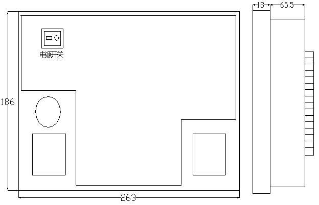
For embedded installation, the overall dimension is 263mm × 186mm × 85mm and the opening dimension is 249mm × 173mm
4.2、Wiring diagram(This drawing is the general terminal drawing, and the specific terminal drawing is subject to the real object)
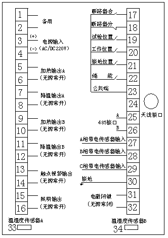
三、Description of display and setting
3.1、Display
High Definition LCD data display. Each time you press the [↓] key, scroll down one screen, and automatically return to the first screen at the last screen. The factory set auto cycle display time is 8 seconds.
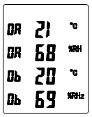
3.1.1、Temperature and humidity display (as shown in Figure 1)
The temperature of circuit a is 21 ℃ and the humidity is 68%; the temperature of circuit B is 20 ℃ and the humidity is 69%.
(Figure 1)
3.1.2 wireless contact temperature display
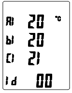
Figure 2 shows that the temperature of the first channel (A1) is 20 ℃, the temperature of the second channel (B1) is 20 ℃, the temperature of the third channel (C1) is 21 ℃, and ID indicates that the communication address is 00.
(Figure 2)
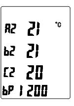
Figure 3 shows that the temperature of channel 4 (A2) is 21 ℃, that of channel 5 (B2) is 21 ℃, that of channel 6 (C2) is 20 ℃, and that of BP is 1200 bps.
(Figure 3)
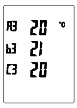
Figure 4 shows that the temperature of channel 7 (A3) is 20 ℃, that of channel 8 (B3) is 21 ℃, and that of channel 9 (C3) is 20 ℃.
(Figure 4)
3.1、Setting instructions
Press the set key to enter the setting menu, and the system will enter the 00 screen (as shown in Figure 5), and "1111" will appear on the screen. Move the cursor and increase the value of the key by pressing the key [↑] to change "1111" to "1116" (password 1116), and press the set key to confirm to enter the 01 screen. If the password is wrong, it will return to the temperature and humidity display screen.
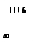
Figure 5
01 screen can set the upper and lower limit values of temperature / humidity (as shown in Figure 6). A-line: set the upper limit value of temperature to 15 ℃ and the lower limit value to 05 ℃; B-line: set the upper limit value of humidity to 95% and the lower limit value to 85%. Move the cursor circularly by pressing the key [↑] and increase the value by pressing the key [↓] to change the number to be set. Press the set key to store the data and enter the next screen at the same time.
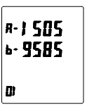
Figure 6
02 screen can set the exhaust data, communication address and baud rate (as shown in Figure 7). F-Line: set the upper limit value of exhaust air to 60 ℃ and the lower limit value to 50 ℃; DB line: the first two digits are the communication address (when there is a "phone" flashing on the upper right corner of the LCD during communication); the last two digits are the baud rate, which can be set (12 is 1200BPS, 24 is 2400bps, 48 is 4800bps, 96 is 9600bps), and the number to be set can be changed by pressing the key [↑] to move the cursor circularly and the key [↓] to increase the value Press the set key to store data and enter the next screen at the same time.
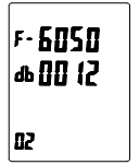
Figure 7
03 screen to 09 screen (reserved): it has been set before leaving the factory, and the customer does not need to set it.
10 screens can be set with wireless temperature measurement alarm data (as shown in Figure 8). Line C1: set the wireless temperature measurement alarm data to 55 ℃ for the upper limit and 50 ℃ for the lower limit. Line C2: reserved.
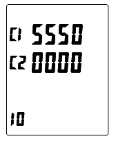
Figure 8
11 screen retention, which has been set before leaving the factory (as shown in Figure 9).
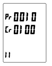
Figure 9
12 screen retention, which has been set before leaving the factory (as shown in Figure 10).
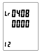
Figure 10
四、Communication
4.1、Introduction
This product is standard equipped with RS485 communication interface, using MODBUS-RTU communication protocol. In theory, up to 32 instruments can be connected on a communication line at the same time. The communication connection should use a shielded twisted pair wire with a copper network, and the wire diameter should not be less than 0.5mm2. When wiring, the communication line should be far away from the strong electric cable or other strong electric field environment, and the maximum transmission distance is 1200 meters. The typical network connection mode is shown in the figure below, and the user can choose other appropriate connection mode according to the specific situation.

Modbus RTU is an international and open fieldbus standard. As a fieldbus protocol that is easy to implement, Modbus has been successfully applied all over the world. Applications include automation in manufacturing processes, process control and building automation. Modbus protocol adopts the communication connection mode of master-slave response on a communication line. First, the host computer's signal is addressed to a unique address of the terminal (slave), and then the reply signal sent by the terminal is transmitted in the opposite direction to the host, i.e. in half-duplex mode.
Modbus protocol only allows communication between the host (PC, PLC, etc.) and terminal devices, and does not allow data exchange between independent terminal devices. In this way, terminal devices will not occupy the communication line during their initialization, but only respond to the query signal arriving at the machine.
Adopt serial communication, 8 data bits, 1 start bit, 1 stop bit, no parity bit.
The up and down commands consist of address code, function code, data area and CRC-16 check code.
The principle of high byte before, low byte after, high word before, low word after (except check code) is adopted.
Frame is the basic unit of information transmission. In Modbus protocol, the frame format of host and slave is the same.
A frame begins with a pause time of at least 3.5 bytes, which also marks the end of the frame. The entire frame must be transmitted as a continuous stream. If there is a pause of more than 1.5 bytes before the frame is completed, the slave will restart the reception of a new frame. The RTU frame format is shown below.
Start
|
Address code
|
Function code
|
Data area
|
Check code
|
End
|
Four byte pause time
|
1 byte
|
1 byte
|
N bytes
|
2 bytes
|
Four byte pause time
|
4.3.1、Address code(Address)
The address code is used to identify which slave communicates with the host. Each slave has a unique address code. The address code sent by the host indicates the slave address to be sent, and the address code sent by the slave indicates the slave address to be sent back. Users can use the address of 1 ~ 247, other addresses reserved.
4.3.2、Function code(Function)
The function code indicates the function to be performed by the slave. The following table lists the function codes supported by the instrument and their definitions and specific operations.
Function code
|
Definition
|
Operation
|
03H
|
Read register
|
Read data from one or more registers
|
10H
|
Write one or more consecutive registers
|
Modification of fixed value
|
4.3.3 Data Area
Data areas vary from function code to function code. These data can be numeric values, reference addresses, etc. For example, function code 03H tells the meter to read the value of the register, then the data area must contain the start address of the register to be read and the read length.
4.3.4 Check code
Checkcheck code is used to judge whether the data received by the host or slave machine is wrong, so that the system communication is more reliable.
Modbus-RTU uses CRC-16 (16-bit cyclic redundancy check code) check method, including 16-bit binary. The CRC check code is calculated by the sender and placed at the end of the message being sent. The receiver recalculates the check code of the received message and compares it with the received check code. If the two do not match, it indicates a communication error.
Error handling
When the meter detects any error other than the error of the check code, it will send back information to the host. The highest position of the function code is 1, that is, the function code sent back from the machine to the host is added 128 on the basis of the function code sent by the host. The format of the error message returned from the machine is as follows:
Address code
|
Function code (the highest bit is 1)
|
Error code
|
Check code
|
Low byte
|
High byte
|
1 byte
|
1 byte
| 1 byte | 1 byte |
1 byte
|
The error code is as follows:
01H
|
Illegal function code
|
The received function code is not supported by the meter
|
02H
|
Illegal data address
|
The received data address is out of the range of the instrument
|
03H
|
Illegal data value
|
The received data value exceeds the data range of the corresponding address
|
4.5.1、Read register (function code 03h)
For example, the first three high voltage contact temperature registers of the device with communication address of 01h need to be read
(Hexadecimal send) 01 03 01 08 00 03 85 F5
Master station sending
|
Number of bytes
|
Send content
|
Explain
|
Start character
| |
Four byte pause
|
The pause time between the beginning of a data frame
|
Slave address
|
1
|
01H
|
Send to slave device with address 01h
|
Function code
|
1
|
03H
|
Read register function code
|
Start register address
|
High byte
|
2
|
01H
|
Starting address of data (register 0108h is the first contact temperature)
|
Low byte
|
08H
|
Number of registers
|
High byte
|
2
|
00H
|
Read 3 registers (06 bytes in total)
|
Low byte
|
03H
|
Check code
|
Low byte
|
2
|
85H
|
CRC check code calculated by master station
|
High byte
|
F5H
|
Terminator
| |
Four byte pause
|
Interval pause time at the end of data frame
|
Frame format returned from slave station:
(Hexadecimal send) 01 03 06 00 30 00 2F 00 2F 11 64
Slave response
|
Number of bytes
|
Send content
|
Explain
|
Start character
| |
Four byte pause | The pause time between the beginning of a data frame |
Slave address | 1 | 01H | From slave device with address 01h |
Function code | 1 | 03H |
Read register function code
|
Number of bytes read | 1 | 06H |
A total of 6 bytes of data were read |
First register data | High byte | 2 | 00H |
The measured value corresponds to the register address of 0108H, the low
byte is valid, the hexadecimal number 30H converted to decimal is 48, minus the corrected value 20 is the actual contact temperature of the first way 28℃.
|
Low byte | 30H |
Second register data | High byte | 2 | 00H |
The measured value corresponds to register address 0109H, low byte valid,
hexadecimal number 2FH converted to decimal 47 minus the modified value 20 is the second way actual contact temperature 27℃.
|
Low byte | 2FH |
Third register data | High byte | 2 | 00H | The measured value corresponds to the register address of 010Ah, which is
valid in low bytes, and the hexadecimal number 2FH converted to decimal is 47 minus the modified value 20 which is the actual contact temperature of
the third way 27 ° C. |
Low byte | 2FH |
Check code | Low byte | 2 | 11H | The CRC check code calculated by the slave station |
High byte | 64H |
Terminator | |
Four byte time
pauses | The pause time between the end of a data frame |
4.5.2、Write register (function code 10h)
For example, the communication address of the device needs to be changed from 01h to 16h, and the master station sends the frame format as follows:
(Hexadecimal send) 01 10 10 60 00 01 02 00 16 3F FF
Master station sending | Number of bytes | Send content | Explain |
Start character | | Four byte pause | The pause time between the start of a data frame |
Slave address | 1 | 01H | To a slave device at address 01H |
Function code | 1 | 10H | Write the register function code |
Start register address | High byte | 2 | 10H | The write register starts at 1060H |
Low byte | 60H |
Number of write registers | High byte | 2 | 00H | The number of write registers is 1 |
Low byte | 01H |
Number of bytes | 1 | 02H | The register data is 2 bytes in total |
Data written | High byte | 2 | 00H | The data written is 0016h (new communication address) |
Low byte | 16H |
Check code | Low byte | 2 | 3FH | CRC check code calculated by master station |
High byte | FFH |
Terminator | | Four byte pause | Interval pause time at the end of data frame |
The slave station returns the frame format:
(Hexadecimal receive)16 10 10 60 00 01 06 30
Slave response | Number of bytes | Send content | Explain |
Start character | | Four byte pause | The pause time between the beginning of a data frame |
Slave address | 1 | 16H | Update slave device address to 16h |
Function code | 1 | 10H | Write register function code |
Start register address | High byte | 2 | 10H | The starting register address is 1060h |
Low byte | 60H |
Number of write registers | High byte | 2 | 00H | The number of write registers is 1 |
Low byte | 01H |
Check code | Low byte | 2 | 06H | CRC check code calculated by slave station |
High byte | 30H |
Terminator | | Four byte pause | Interval pause time at the end of data frame |
五、Appendix
5.1、Read only register address table
Register address | Data format | Function | Data item name | Remarks |
Read | Write |
0101H | XXXX | * | | Switch input status | HEX |
0102H | XXXX | * | | Relay output status | HEX |
0103H | XXXX | * | | First temperature | HEX,[(hex to DEC) - 20] ℃ |
0104H | XXXX | * | | First way humidity | HEX |
0105H | XXXX | * | | Second circuit temperature | HEX,[(Hex to DEC) - 20] ℃ |
0106H | XXXX | * | | Second way humidity | HEX |
0107H | XXXX | * | | Room temperature | HEX,[(hex to DEC) - 20] ℃ |
0108H | XXXX | * | | High voltage contact temperature 1 (A1) | HEX,[(hex to DEC) - 20] ℃ |
0109H | XXXX | * | | High voltage contact temperature 2 (B1) | HEX,[(hex to DEC) - 20] ℃ |
010AH | XXXX | * | | High voltage contact temperature 3 (C1) | HEX,[(Hex to DEC) - 20] ℃ |
010BH | XXXX | * | | High voltage contact temperature 4 (A2) | HEX,[(hex to DEC) - 20] ℃ |
010CH | XXXX | * | | High voltage contact temperature 5 (B2) | HEX,[(hex to DEC) - 20] ℃ |
010DH | XXXX | * | | High voltage contact temperature 6 (C2) | HEX,[(Hex to DEC) - 20] ℃ |
010EH | XXXX | * | | High voltage contact temperature 7 (A3) | HEX,[(hex to DEC) - 20] ℃ |
010FH | XXXX | * | | High voltage contact temperature 8 (B3) | HEX,[(hex to DEC) - 20] ℃ |
0110H | XXXX | * | | High voltage contact temperature 9 (C3) | HEX,[(hex to DEC) - 20] ℃ |
0111H | XXXX | * | | High voltage contact temperature 10 (A4) | HEX,[(hex to DEC) - 20] ℃ |
0112H | XXXX | * | | High voltage contact temperature 11 (B4) | HEX,[(hex to DEC) - 20] ℃ |
0113H | XXXX | * | | High voltage contact temperature 12 (C4) | HEX,[(hex to DEC) - 20] ℃ |
5.2、Writable register address table
Register address | Data format | Function | Data item name | Remarks |
Read | Write |
1060H | XXXX | * | * | Device address | HEX |
1061H | XXXX | * | * | Baud rate | BCD code, low byte 12, 24, 48, 96, corresponding to the baud rate of 1200, 2400, 4800, 9600bps respectively |
1063H | XXXX | * | | Cycle time (seconds) | BCD code, low byte valid |
107EH | XXXX | * | * | Upper temperature limit | Hex, [(hex to DEC) - 50] ℃ |
107FH | XXXX | * | * | Upper humidity limit | HEX |
1080H | XXXX | * | * | Exhaust upper limit | Hex, [(hex to DEC) - 50] ℃ |
1081H | XXXX | * | * | Contact alarm lower limit 1 and upper limit 1 | Hex, high byte is the lower limit of alarm, low byte is the
upper limit of alarm |
1082H | XXXX | * | * | Contact alarm lower limit 2 and upper limit 2 | HEX,The high byte is the lower alarm limit and the low byte is the upper alarm limit |
5.3、Analysis of status word
The operation display status can be viewed by reading the register with address 0101h (i.e. switch input status word)
Analysis of low byte of
register corresponding to
switch input | 0101H | 
|
No.0(B0): indication of closing position of circuit breaker 0—Branch 1—Close |
No. 1(B1): circuit breaker position indication 0—Branch 1—Close |
No. 2(B2): test position indication 0—Branch 1—Close |
No. 3(B3): working position indication 0—Branch 1—Close |
No. 4(B4): grounding position indication 0—Branch 1—Close |
fNo. 5(B5): energy storage position indication 0—Branch 1—Close |
No. 6(B6): undefined |
No. 7(B7): undefined |
For example, if the data read out from register 0101H is 0004 and the low byte is converted into binary number 00000100, it can be seen that only the second bit (B2) of the data is 1, which means that the test position indicates the sum and other positions are points at this time. If h read data from the register 0101 to 0029, converts the low byte to a binary number is 00101001, you can see in the data 0 (B0) and third (B3), 5 (B5) to 1, said circuit breaker closed position indicator for us at this time, work position indicator for us, and energy storage position indicator for other location for points.
In addition, the low byte corresponding to register address 0102H is the output of the relay. The output state of each relay can be viewed by reading the low byte of register address 0102H, and its data is defined as:
Relay output corresponds to
the low byte resolution of
the register | 0102H | 
|
No.0(B0):A channel heating relay 1—output 0—No output |
No.1(B1):A cooling relay 1—output 0—No output |
No.2(B2):B channel heating relay 1—output 0—No output |
No.3(B3):B channel cooling relay 1—output 0—No output |
No.4(B4):Contact alarm relay 1—output 0—No output |
No.5(B5):Lighting switch relay 1—Open 0—Shut |
No.6(B6):Electromagnetic locking relay 1—output 0—No output |
No.7(B7):undefined |
六. Transportation and storage
The products shall be transported and unpacked without severe impact, and shall be transported and stored according to GB/T15464 General Technical Conditions for Instrument Packaging. The products should be stored in the original package, where the ambient temperature is -40℃ ~ +70℃, the relative humidity is not more than 85%, and there is no corrosive gas in the air. The products shall be stored in the warehouse and placed on the platform with a stacked height of no more than 5 cartons. After unpacking, the stacked height of the products packed individually shall not exceed 3 cartons.
七. Warranty Period and Order Description
Within 12 months from the date of leaving the factory, the manufacturer shall repair or replace the products free of charge if the users find that the products have defects in function, appearance or do not conform to the technical indicators during the operation and use (except for the damage caused by man-made damage and operation error) in accordance with the requirements stipulated in the instructions. When ordering, please specify the required model and function requirements, so as to provide you with more accurate products.
八. Matters needing attention
Installation and use matters needing attention
Read this operation manual carefully before use;
The corresponding temperature and humidity sensor model WS-02;
When playing pressure, pull out all terminals;
When in use, check whether all wiring terminals are tightly inserted;
When installing the transmitter module, please open the switch of the transmitter module first. The number of the transmitter module shall correspond to the circuit value on the main engine body and on the same side of the cabinet. When fixing the transmitting module, the force should be moderate and should not be tied too tightly.
Schedule: Common Troubleshooting
Common problem | Cause analysis | Simple solution |
No display after power supply | The power supply is not added to the device | Check whether the correct working voltage is applied to the two terminals of the working power supply of the device. |
There is no status display | It's not connected properly | Check whether terminal 17-23 of the device has been plugged in. If it has been plugged in, short the rear common terminal and terminal 17-22 with short wiring respectively, and check whether there is corresponding status indication. |
The temperature and humidity are not displayed or there is one way of temperature and humidity not displayed | Does the model of temperature and humidity sensor match | Check whether it is ws-02 temperature and humidity sensor. |
The host, sensor cable and temperature and humidity sensor are not well connected | Check whether the host, sensor wire and temperature and humidity sensor are firmly connected. |
The switching value does not change | Inaccurate switch action voltage | Check whether the external node type matches the rated parameters of the equipment; check whether the external wiring is correct. |
No control command received | Check whether the communication line is correct. |
Unable to communicate | The communication address of the device is incorrect | Check whether the device address is consistent with the definition. |
The baud rate of the device is incorrect | Check whether the baud rate of device communication is consistent with the definition. |
Communication line interruption | Check if the communication cable is disconnected. |
Temperature sensor data not received | The setup address has been changed | Enter the setup menu to see if the address is correct. |
Low line load | Check the temperature data after the line load returns to normal. |
The number of the temperature sensor does not correspond well with the circuit value of the main engine | Check whether the number of the temperature sensor and the host circuit value are one-to-one corresponding and installed in the same switch cabinet. |


