1 Overview
It is widely used in substations to protect, monitor and parallel the voltage of secondary windings of voltage transformers. It can operate normally in the power system for a long time.
2. Product structure characteristics
2.1 The front of the cabinet is a single-opening glass door, and the rear is a double-opening steel door, and there are two rows of long ventilation holes on the upper and lower sides.
2.2 When the cabinets are arranged in a row for installation, the side doors between adjacent cabinets can be detached, and adjacent cabinets can be connected by gong rods, and there are threading holes on the sides of the cabinets.
2.3 The lower part of the front panel of the cabinet is provided with threading holes for debugging and testing wiring.
2.4 The terminal block is installed on the terminal rails on the left and right sides. The wiring in the cabinet is arranged on the inside of the terminal block, and the user cables are arranged on the outside of the terminal block. 2.5 The grounding bronze plate in the cabinet is installed in the air with a porcelain bottle, and there is no electrical connection with the cabinet. In addition, there are no less than 3 sets of M6 and M8 grounding bolts connected to the grounding grid in the cabinet.
2.6 40W explosion-proof lamp is used for lighting in the cabinet, and the switch of the lamp is manually controlled by an air switch.
2.7 The top of the screen is equipped with 4 independently controlled fans and reserved ventilation holes to prevent dust and heat dissipation.
2.8 The cabinet body is a fully enclosed combined structure, the cabinet door is a glass door, and the mounting plate is fixed in a rotatable frame.
2.9 The outer shell of the cabinet is made of a cold-rolled thin steel plate that has been optimally processed, and its thickness is not less than 1.5-2mm, and its structure is sufficiently reinforced to ensure a flat surface and rigidity, and to prevent vibration during shipment and installation.
2.10 The cabinet door is made of a flat plate. In order to ensure the rigidity, the edge of the door is rolled back into a rectangle, the door is straight, and concealed hinges are installed. The handle of the door adopts a form acceptable to the user.
2.11 The top and bottom adopt bar-type mortise locks. When the door is opened, the bottom of the cabinet is provided with a metal door sill with a height of no more than 20mm. The purpose is only to set a permitted barrier at the opening of the cabinet.
2.12 The bottom surface of the cabinet has a supporting board for installation. The cabinet is completely rectangular, and the diagonal error conforms to the national standard, so that it can be well matched with the adjacent cabinet.
2.13 The material selection and manufacturing process of the complete cabinet make the exterior and interior of the cabinet neat and tidy. There are no welds, rivets or bolt heads on the exterior of the cabinet, and the entire outer surface of the cabinet is truly smooth.
2.14 The design insulation level of the voltage inside the cabinet is AC 600V.
2.15 Basic size and color width: 800mm depth: 600mm height: 2260mm cabinet color is RAL7035.
2.16 The appearance coating film of screen frame, door, top cover, etc. is smooth, not only the light and color are consistent, and there is no pores, cracks, scars, rust spots.
2.17 A copper-core grounding busbar is installed at the bottom of each cabinet. The minimum cross-sectional area of the copper busbar is 100mm2, and the screen shell has a grounding screw.
2.18 Every bolt joint, bushing and tap (except the control and instrument loop ground connection) connected to the ground bus shall comply with national standards.
2.19 The grounding device is marked, the mark will not disappear, the grounding bus is marked as TE, the grounding screw is marked as PE, and the grounding uses jumper wires or connecting pieces, so that the grounding point can be folded.
2.20 The insulation resistance between the two independent circuits that are not electrically connected in the cabinet, and between each live circuit and the screen frame, under normal atmospheric conditions, is not less than: 50~100MΩ, under humid and hot conditions (temperature 40±2℃, Relative humidity 90%~98%, atmospheric pressure 86~108KP2) not less than 1MΩ.
2.21 Under normal atmospheric conditions, between the two independent circuits that are not electrically connected on the screen, and between each live circuit and the screen frame, it can withstand a test of 50Hz and an AC test voltage of 2500V (effective value) for 1 minute, no shock Puncture or flashover phenomenon (excluding weak current and DC part).
2.22 Terminals
The rated value of all terminals is 1000V, 10A, crimp type terminals, using Weidmüller terminals. The selection of the terminal model matches the nature of the loop, and the terminals of the current and voltage loop can be connected to a cable core of not less than 4 mm2. The secondary circuits of CT and PT should provide standard test terminals to facilitate disconnecting or short-circuiting the input and output circuits of the device. Only one wire can be connected to one terminal. The terminals are clearly numbered, and there is sufficient insulation between the terminal blocks. The terminal blocks are arranged in sections according to their functions. Isolated terminals should be set between each circuit and between the power circuit and other terminals. The terminal block has 20% of the total number of terminals. The terminal is used for transfer or transition during design. Leave enough space between the terminal blocks to facilitate the connection of external cables. The terminal block is firmly fixed, so that it will not become loose due to vibration, heat, etc., and at the same time, it can be easily inspected and maintained.
3. Voltage monitoring and harmonic elimination circuit
A voltage relay or voltage monitoring device is used to monitor whether the metering circuit voltage disappears, and a zero sequence voltage relay is used to monitor whether the open triangle of the voltage transformer is zero sequence overvoltage. The harmonic elimination device is used to eliminate the harmonics of the open triangle of the voltage transformer. Voltage monitoring and harmonic elimination loop power supply are controlled by independent air switches, which is convenient for equipment maintenance.
4. Voltage parallel circuit
A relay or voltage parallel device is used to parallel the two busbar voltages, and the voltages of the voltage transformer protection circuit, measurement circuit and metering circuit are respectively paralleled. The transfer switch realizes the local or remote parallel. Each parallel loop control power supply is controlled by an independent air switch, which is convenient for equipment maintenance.
5. Cabinet technology
5.1 Cabinet material: The frame is made of 2mm cold rolled steel plate, and the plate is 1.5mm cold rolled steel plate.
5.2 Cabinet structure: the front of the cabinet is a single glass door, and the rear is a double metal door or revolving door; detachable baffles are installed on both sides; each mounting plate is made of separate panels; the top of the cabinet is equipped with a cover plate with knockout holes and To install the bus terminal guide rail, additional lifting screws are required.
5.3 Cabinet surface treatment: use plastic spray treatment.
5.4 Cabinet installation accessories: Two-meter-long terminal rails are installed on the left and right sides of the back; the corners of all cabinet doors and the cabinet body need to be welded with an M6 grounding galvanized screw and equipped with hexagonal nuts. A grounding copper bar is installed in the cabinet through an insulating column.
5.5 Cabinet size and color: according to order requirements.
6. Wiring process and terminals: in line with current national standards and regulations.
6.1 AC voltage circuit. Wire color: Phase A yellow; Phase B green; Phase C red; Phase N light blue; Wire specifications: 2.5mm2 strands.
6.2 AC and DC power circuit. 220VL or DC+ uses brown, 220VN or DC- uses blue; wire specification: 1.5mm2 strands.
6.3 Grounding: 4mm2 multi-strand yellow-green waterline.
6.4 Other circuits: 1.5mm2 stranded black wire is used.
6.5 Wire connection method: use crimping, welding or plugging, and comply with its own standards; all wires have no joints, and the wires in the cabinet are connected through the terminal block or equipment connection point. The connections of all terminals are firm and reliable. One terminal or connection point can be connected to a maximum of 2 cable cores.
6.6 Conductor profile: the insulation layer is made of flame-retardant or fire-resistant insulation material, and the insulation layer is wrapped with a copper core.
6.7 Wire placement: all wires shall be covered with groove tubes after passing through the wire grooves, and the exposed wires shall be tied together with wire ties. After being wound with winding tubes, they shall run horizontally or vertically.
6.8 Terminal model: All terminals adopt Phoenix voltage terminals.
6.9 The shorting terminals are connected by copper connecting pieces, and a separator is added between the two groups of connectable voltage terminals.
7. Nameplate identification
7.1 A sign is attached to the horizontal brow on the front of the cabinet to clearly indicate the specific name and type of the cabinet.
7.2 The company name is printed on the bottom of the front of the cabinet.
7.3 The circuit number and unit name of the installation unit are clearly marked on the top of the installation unit, and all terminals are marked with the terminal code number with a sign. Relative numbering is adopted at both ends of the wire.
8. Overhaul and maintenance
In order to facilitate future inspection and maintenance, the cabinet is equipped with lighting lamps through the air switch.
9. Ordering instructions
When ordering, please specify the model, quantity, dimensions, color, main ordering parameters and special requirements of the cabinet.
1. Technical conditions
1.1 Technical regulations that the PT interface cabinet complies with
JB5777.2 "General technical conditions for secondary circuit control and relay protection screens (screens, sets) of power systems"
JB5777.3 "Basic test method for secondary circuit control and relay protection screen (screen, platform) of power system"
1.2 Environmental benchmark conditions
Environment temperature: 20±2℃
Relative humidity: 45%~75%
Atmospheric pressure: 86~106KPa
1.3 Normal use conditions
Ambient temperature: -10℃~+50℃
Relative humidity of environment: not more than 90%
Atmospheric pressure: 86~110KPa
Limit temperature during storage and transportation: -25℃~+70℃
The altitude of the place of use: no more than 2500 meters
The surrounding medium of the operating environment has no explosion hazard; it does not contain corrosive gas; the concentration of conductive dust contained should not reduce the insulation level below the allowable limit value.
1.4 Insulation resistance: After all terminals are short-circuited to the ground, use a 1000MΩ megger to measure the insulation resistance ≥10MΩ.
1.5 Insulation withstand voltage: After all terminals are shorted to the ground, the withstand voltage is 1.5KV, and there is no breakdown in one minute.
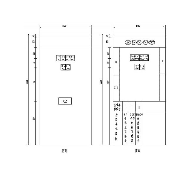
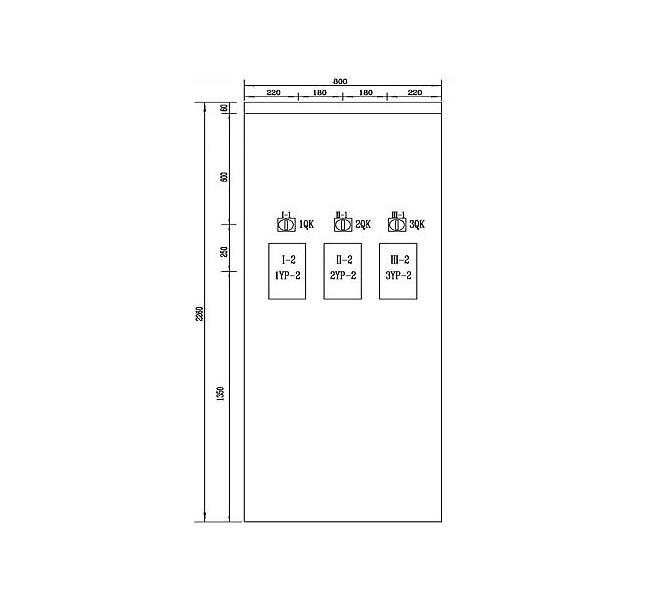
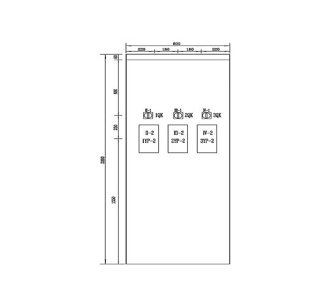
2. Typical design drawings of 500KV, 220kV, and 110kV PT interface screens are as follows:
Main transformer and 35kV PT interface cabinet layout drawing (500KV station)

220KVPT interface cabinet cabinet layout drawing (220KV station)

110KVPT interface cabinet layout (220KV station)

The layout of the 10KVPT interface cabinet (220KV station)

Layout of PT interface cabinet (110KV station)


 Language