1 Introduction to the device
The secondary AC power distribution panel is based on the Ministry of Energy "Power Plant, Substation Engineering and Relay Protection Test Instrument Configuration Quota" issued by the Ministry of Electric Power Industry "Power System Relay Protection and Safety Automatic Equipment Anti-accident Measures" Products designed and manufactured by relevant regulations. It provides a reliable, stable and convenient AC power supply for the work of the on-site secondary equipment, and provides a reliable guarantee for meeting the working power requirements of the on-site secondary equipment and ensuring the safety of personnel and equipment.
1.1 Purpose
This equipment is suitable for power plants, substations and large and medium-sized industrial enterprises, and can be used as a general-purpose AC power distribution panel for secondary equipment.
1.2 Features
1.2.1 It adopts dual power supply, which can be switched manually and automatically. The use of contactors can switch with load to ensure the reliability of power supply.
1.2.2 The control of AC power supply adopts high-breaking miniature circuit breaker, which has the advantages of rapid action, high sensitivity, reliable action, etc., and has the functions of short circuit and overload automatic tripping.
1.2.4 There are many feeders.
1.2.5 It has the function of short circuit and overload trip alarm indication.
2 Product structure
2.1 Screen body structure, surface coating, electrical clearance and creepage distance, anti-static measures, electrical performance, wire laying, temperature rise, heat resistance, mechanical performance and other requirements, all meet the requirements of the corresponding clauses of DL/T720-2000. A dedicated grounding copper bar with a cross-section of 100 square millimeters is installed in the screen.
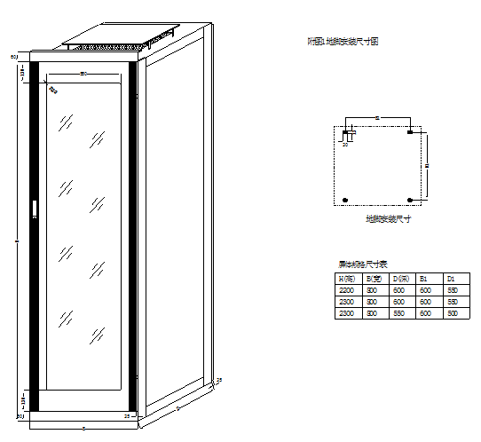
2.2 Adopt PK-10 fully enclosed cabinet structure, front and rear doors with locks, and the screen body is made of plates. The screen structure diagram of the whole machine is shown in Figure 2.
2.3 Main internal components: automatic air switch, leakage protection switch, voltmeter, contactor, indicator light and other components.
2.4 The analog circuit is drawn on the screen to make it easy for the operator to identify and avoid misoperation;
2.5 The instrument, indicator light and control switch are installed on the front panel, and the input and output wires can be connected through the terminal block behind the screen.
3 Equipment electrical performance
3.1 Insulation resistance: Under standard test atmospheric conditions, the insulation resistance between each circuit of the device and the housing is not less than 10MΩ; the insulation resistance between each independent circuit is not less than 10MΩ.
3.2 Dielectric strength: Under standard test atmospheric conditions, the above-mentioned circuits and each independent circuit can withstand AC 50Hz, voltage 2kV (effective value), and the test lasts 1min without insulation breakdown or flashover.
3.3 Impulse voltage: Under standard test atmospheric conditions, each AC circuit and DC circuit should be able to withstand a standard lightning wave short-time impulse test of 5kV (peak).
3.4 The AC circuit uses Merlin Gerin C65N series small automatic switch, the mechanical life is more than 20,000 times on and off, and the instantaneous breaking current can reach (4~7) Ie.
4 Conditions of use
4.1 Use indoors with good indoor ventilation.
4.2 The altitude does not exceed 2000 meters.
4.3 Ambient air temperature: -10℃~+55℃.
4.4 Relative humidity: 5% to 95% (there is neither condensation nor freezing inside the device).
4.5 Vibration that exceeds the severity level 1 specified by IEC60255-21-1 shall not occur at the place of use.
4.6 The difference between the installation inclination and the plumb line is no more than 5. .
4.7 The place of use should have facilities to protect against rain, snow, wind and sand. The grounding resistance of the place of use should meet the requirements of 4.4 in GB/T 2887-2000 and the relevant requirements of the power system for lightning protection and grounding of the substation.
5 working principle
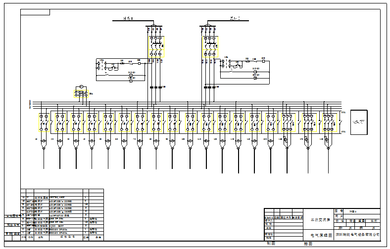
5.1 Electrical schematic diagram (see Figure 3)
5.2 Circuit introduction
5.2.1 The power input adopts three-phase four-wire 220V/380V dual-channel AC power supply, and the two power sources are automatically switched on each other.
5.2.2 The contactor to the busbar and the feeder output are equipped with high-breaking circuit breakers, which can facilitate the power-off maintenance of each circuit.
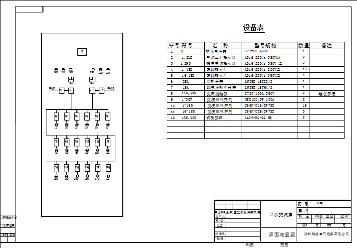
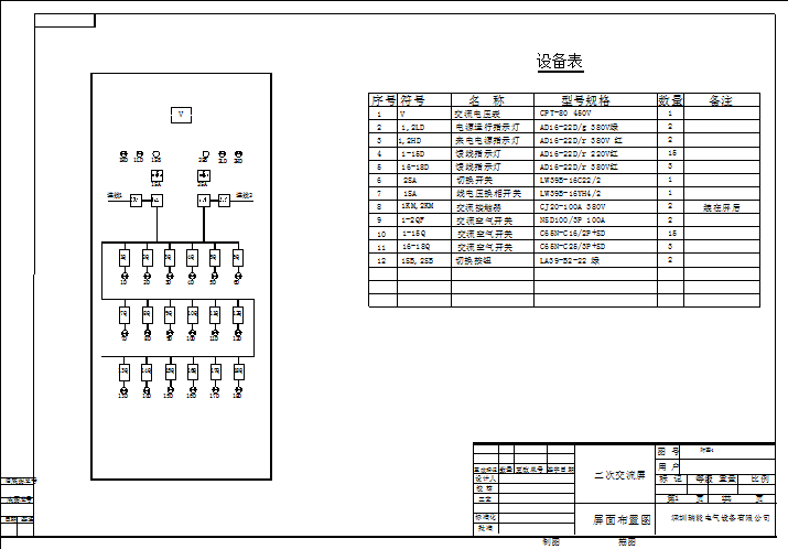
5.2.3 The voltmeter directly monitors the three-phase output voltage and reflects the power supply status. The plane simulation diagram is shown in Figure 4 and the terminal block diagram is shown in Figure 5.
5.2.4 Each feed switch has a set of trip alarm contacts, which can realize the alarm function.
6 Main technical indicators
6.1 Communication section
6.1.1 Rated input voltage: three-phase four-wire 220V/380V, frequency 50Hz;
6.1.2 Rated output voltage: 220V/380V, three-phase four-wire, a total of six outputs;
220V, single-phase AC, a total of six outputs.
7 Installation and use
7.1 The screen body is fixed, the ground terminal button is reliably connected to the ground grid, and then the three-phase AC power is introduced into the terminal block A1, B1, C1, N1 or A2, B2, C2, N2 behind the screen. The terminal block diagram is shown in Figure 5. Show.
7.2 According to the screen simulation diagram (see Figure 4), check that all control switches are in the off position. Check that all wiring is not loose or fall off.
7.3 Close the AC power input switch 1QF. At this time, the power indicator light 1HD glows, and 1ZJ pulls in; move the 1SA handle to the left (or move the 1SA handle to the right, press the 1SB button), 1KM pulls in, 1LD glows, 1ZJ, 1KM normally closed contact opens, disconnect the 2KM closing coil power supply, 1KM operation, power supply No. 1; close the AC power input switch 2QF, at this time the power indicator 2HD lights up, move the 2SA handle to the left (or 21SA Move the handle to the right and press the 2SB button), when the No. 1 power supply loses power, 1ZJ loses power, 1KM loses power and trips, 2KM pulls in, 2LD shines, and No. 2 power supply runs; 1KM and 2KM have an electrical interlock relationship, 1QF, When 2QF is closed at the same time, only one contactor can be closed at the same time, not at the same time, so as to ensure one power supply. The 1SA and 2SA handles are in automatic position on the left, manual position on the right, and off position in the middle position. In the middle position, neither 1KM nor 2KM can be pulled in, and the power supply cannot be supplied.
7.4 By turning the different gears of the change-over switch, the ABC three-phase line voltage can be viewed respectively.
7.5 Any circuit breaker tripping caused by overload, short circuit, grounding, etc. can be indicated by the alarm indicator.
8 Ordering instructions
8.1 The screen body structure is PK-10 standard design, and there are additional sealing plates on both sides. Please refer to Figure 2 to indicate the screen body size when ordering.
8.2 The company can design AC power supply panels for secondary equipment with different structures according to user requirements. Users should specify specific requirements (or provide drawings) when ordering.
8.3 The company can design power supply screens with different performances on behalf of users (or customize according to drawings provided by users).
8.4 When ordering, the screen size, color, order quantity, etc. should be indicated.
8.5 The configuration in the manual is subject to change without notice, and the drawings and data provided with the goods shall prevail.
8.6 The warranty period of the secondary equipment AC power distribution power supply equipment is one year from the date of commissioning. If there is a quality problem within one year, the manufacturer will provide the components free of charge, and the user will replace it by themselves.
8.7 This equipment is a maintenance-free product. After one year of operation, if the equipment fails and requires maintenance by the manufacturer, the manufacturer charges the service cost. If there is no special reason, arrive at the equipment site within 96 hours.
9 Figures
Attached picture 1 2 screen body picture.dwg

Figure 3 Electrical schematic diagram.dwg

Figure 4 Plane simulation diagram.dwg

Figure 5 Terminal diagram.dwg


